
Device Link Profiling
Introduction
In a normal color correction workflow, input colors are first converted to a device independent color space (such as Lab) through input profiles, and then to the output color space through output profiles.
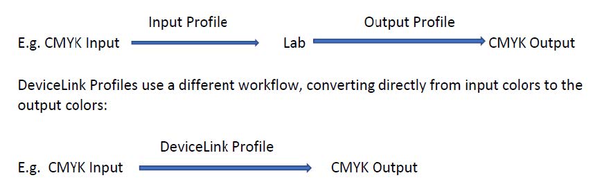
This direct conversion facilitates some special handlings such as preserving pure colors. It can also be use to simulate the output from one printer on another one. These account for 2 types of DeviceLink profiles that can be created with Flexi DeviceLink Profiler, input to output DeviceLink, and printer to printer DeviceLink.
Most of the functions can be found in the software CoPrA from ColorLogic, and here is a link to their documentation with more detailed descriptions:
http://onlinehelp.colorlogic.de/en/copra-devicelink-profiling/
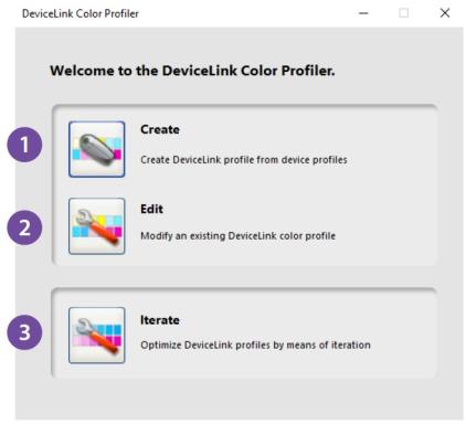
Creating Profiles
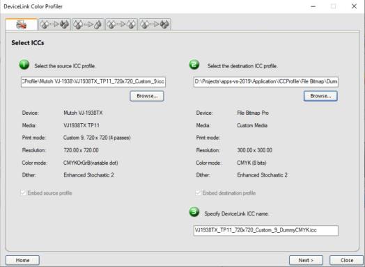
1) To create a DeviceLinkprofile, first select a source and a destination ICC profile. The source profile can be an output profile for another printer, or a CMYK or RGB input profile.
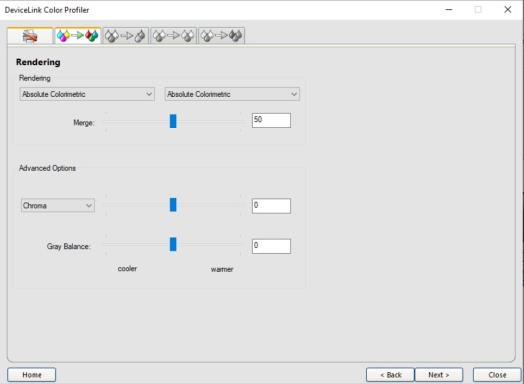
2) Next, specify rendering options, such as: Rendering intents, Chroma, saturation and lightness adjustment, graybalance adjustment.
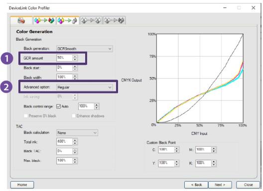
3) Next step is to specify black generation options. Most of them are similar to the regular Colorprofiler, and here are some of the additional ones:
1. GCR amount: Defines the amount of CMY that is replaced by black. At 0 only a low GCR amount is used which mainly impacts the shadows whereas at 100 a very strong GCR is used which effects the shadows and the highlights.
2. Advanced Option:
Regular: No special GCR processing
Preserve Separation: Preserves the ratio between the black channel and CMY composed black.
Note: The black generation mode Preserve Separation is especially important for conversions between similar CMYK printing processes (conversions between two offset presses or two inkjets of the same model etc.), because it ensures that the ratio between CMY and black which is used to generate grayis maintained in the colorconversion.
Preserve black: Linearizes the black value of the source profile and retains the black channel.
Save ink: Replaces CMY colors by black to save CMY inks.
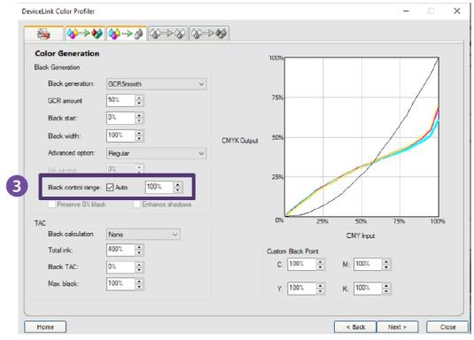
3. Black control range: Controls the transition to black. If black exceeds the limit, CMY colorants will not be modified and black is linearly added. Up to the specified value black will be calculated accurately. A value of 0% indicates that only CMY will be converted whereas black will be linearized. If a proof requires an exact colorimetric reproduction the slider should be set to 100%. 80% is a good value to achieve a smooth transition in the shadows. We recommend to activate the checkbox Auto.
4. Black Calculation:
Auto: The calculation of the optimal black point (dark and neutral) is based on the target profile. The values entered for Black TAC and Max.Black define limits which are not exceeded but may be lower if technically possible. All channels are used to generate the black point (Black TAC), therefore individual channel editing is disabled. This mode will not use any Multicolor channels beside the first four channels (usually CMYK).
Note: If no default value for the Black TAC is defined, it is recommended to use 400% as a starting point for the calculation.
Balance CMY: This setting adapts the CMY values to a pre-defined Max.Blackvalue and generates a neutral black point. Define the Black TAC and TAC in accordance with the printing conditions. The Max.Blackshould be set to the ideal value for your substrate. Similar to the setting Auto those values are regarded as maximum values which may be underrun if a neutral black point is not achievable. Allows customization of the black channel (or in general the 4th channel) and the addition of Multicolor channels.
AutoCMY: This setting locks the black channel and optimizes (reduce+balance) CMY to get a neutral black point.
Target Profile: Calculates a black point based on the values of the target profile.
Target Profile Auto: This setting uses the black point and TAC of the target profile and optimizes it with the "Auto" method
Custom: Allows to define the black point in the input box Custom as CMYK values. The Black TAC value will then be recalculated. Allows editing of all channels.
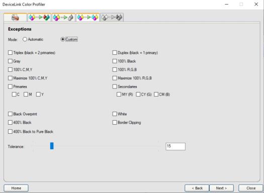
4) Next step is to specify preserving purehue options.
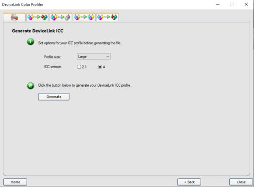
5) The final step is to choose ICC profile options and generate the profile.
Editing Profiles
To edit a DeviceLinkprofile, first browse for the profile, and then following similar steps as above to make changes and re-generate the profile.
Optimizing Profiles through Iterations
This step is to improve a DeviceLink profile by measuring a target with the DeviceLink ICC applied, and regenerate the profile.
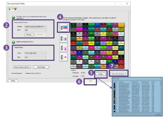
1. Browse for the profile to be optimized.
2. Choose the measurement device.
3. Choose a target and print.
4. Measure the target. The Delta-E (maximum and average) will be calculated and displayed.
5. Click one the button “Details” to view the Delta-E for the individual swatches.
6. To save the profile for this iteration, click on the “Save” Button.
7. To start another round, click on the “Start Next Iteration” button and repeat steps 3 to 6.
Applying DL Profiles in Flexi
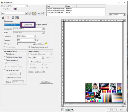
The DeviceLink profiles can be selected from the Color Settings dialog of the RIP and Print dialog (the same dialog where input profiles are selected).
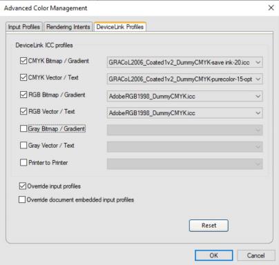
Different DeviceLink ICCs can be assigned to different object types:
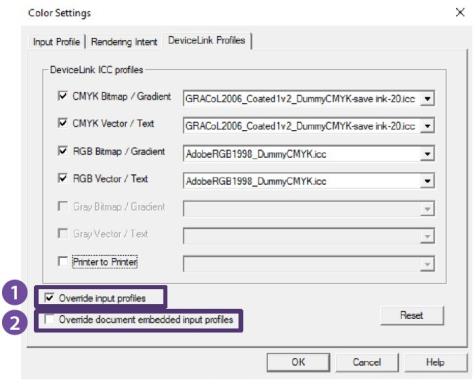
1. Override input profiles: If selected, the input profile selected from the first tab will be ignored and only the DeviceLink profiles will be applied. If it is unchecked, a new DeviceLink ICC will be created connecting the input profiles to the output profiles.
2. Override document embedded input profiles:
If checked, the embedded ICCs in the document will be ignored, and apply only the DeviceLink profiles. If unchecked, a new DeviceLink ICC will be created connecting the embedded profiles to the output profiles.
Note: Even when DeviceLink profiles are used, the linearization profile still comes from the output profile selected in the main tab, so it is important to select the matching destination profile as output profile there.
ApplyingDL Profiles in Production Manager
Similarly, the DeviceLink profiles can be selected from the Color Management tab of the Default Job Properties and Job Properties dialogs.
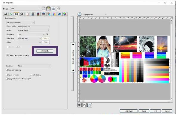
The options are the same as those from the RIP and Print dialog. It is also necessary to select the matching destination profile in the main tab (for linearization ICC).